Production Design

The Gibbs & Cox production design process includes integration of a 3D CAD product model of the vessel, which is based on classed and approved functional drawings, vendor drawings and the shipyard’s build strategy in a configuration optimized for vessel construction.
Production drawings and information are extracted from the 3D product model to support complete construction of the vessel in a sequence and format best aligning with the build processes and work centers at the shipyard. This includes 3D and 2D drawings and CNC data for structural assembly, piping, mechanical, hull outfitting, electrical and HVAC.
Gibbs & Cox uses various 3D CAD/CAM software tools including ShipConstructor and Intergraph. We apply over 30 years of CAD experience and numerous processes to the execution of modeling, drawing extraction, and design control and configuration management under an ISO 9001 quality management system. Our processes are scalable and customizable to a shipyard’s capabilities, preferences, vessel complexity and schedule.
During production design, we follow design for production (DFP) and design for maintenance (DFM) approaches and implement proven methods to improve construction efficiency for the shipyard and reduce lifecycle operating costs.
Components of a fully-integrated production design package include:
Gibbs & Cox uses parametric modeling software to develop fully-faired, three-dimensional models of the complex geometries typical of marine vessels.
In addition to a vessel’s hull, decks, and superstructure, models can include features such as:
We develop drawings that integrate ship systems, penetrations, and structures. We can also incorporate total hull and superstructure outfitting, production details, building standards, weld schedules, system descriptions, classification society documentation, and shipboard drawings.
We fully develop and incorporate a production model and comprehensive construction information into a single package. This provides all information needed to purchase raw material, manufacture parts, fabricate, assemble and erect the entire vessel from stem-to-stern.
We can use the production model to instantly generate several types of reports to provide information on part and assembly weights & centers, interference checks, material ordering schedules and lists, and other supplemental builder-specific information sets.

Ready-to-cut CNC files are developed to suit specific client requirements.
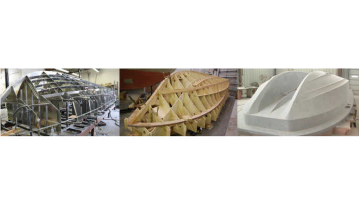
Three-dimensional shaping information and fabrication/assembly instruction packages are developed to facilitate specific construction techniques as required by client practices.

As the production model is developed, accurate dimensional information is integrated, including material thicknesses and dimensional effects of surface finishes and treatments, as well as client and manufacturer tolerance requirements. All parts are assigned numbers and can include markings, registration lines, and reference information. Parts are inventoried, with their numbers and attributes, as individual components of an integral parametric database, ensuring accuracy, control, and documentation of the entire model.
As the development of the model evolves, the inherent adaptability of the parametric modeling allows all modifications to be reliably integrated into the complete package in real time.

The number and complexity of individual assemblies varies from builder-to-builder, based on specific requirements. Individual parts are grouped into assemblies that can be as large as an entire vessel or as small as a single stiffened panel. To facilitate modular construction and modern productivity techniques, a complete assembly hierarchy is created during the modeling process and is used to produce the appropriate assembly drawings relative to each assembly.
To ensure accuracy of fabrication, assembly, and erection processes, several types of construction aids can be provided, including:
The final quality-control tools included with the production information package are customizable to suit individual builder practices and requirements.
Industry-standardized bills of material are provided, documenting all parts and their associated attributes, and can be included as a part of an assembly drawing or as stand-alone reports.
Limitless customization can be incorporated into BOM reports, as required by the builder, and reports can be provided at any stage of the design/build process to support management, procurement, engineering, and build team activities. All loft data required to produce, manufacture, and fabricate structural parts and piping systems are output from the production model. Output is delivered in the form of drawings, reports, and tabulated data files for direct input into CNC machines.
In addition to flat-plate and pipe dimensional information, part curvature and bend geometries (including simple bent/flanged profile information and three-dimensional simple and compound curvature descriptions) are provided.
